
As the core reference component of a linear motion system, the installation accuracy of the linear shaft directly determines the operational stability and service life of the entire mechanical equipment. In practical engineering, how to ensure the installation accuracy of the linear shaft and prevent errors caused by thermal deformation are key skills that engineers must master.
Selection of Supports and Thermal Compensation Strategy
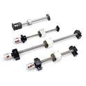
The long-distance installation of linear shafts is highly susceptible to thermal expansion, making the choice of support devices crucial. Typically, support devices are divided into fixed and floating types. The fixed-side support device (e.g., LMF type) fixes the axial position of the shaft using screws or lock nuts, mainly to restrict displacement. The floating-side support device (e.g., LMC type), however, allows for minor axial movement of the shaft. This feature is specifically designed to compensate for errors caused by thermal expansion. For common high-carbon steel shafts, the length expands by approximately 0.012mm per meter for every 1°C increase in temperature. Therefore, for shafts longer than 1500mm, an intermediate floating support device should be installed every 800-1000mm to effectively prevent bending due to thermal expansion and contraction, ensuring the shaft remains perfectly straight.
Installation Accuracy: Control of Parallelism and Coaxiality
Installation errors can severely affect the performance of the linear shaft system, even leading to premature wear of the bushings. When installing two parallel linear shafts, the parallelism error should be strictly controlled within the range of 0.02-0.05mm/meter. If the parallelism error is too large, it will increase friction between the slider and the bushing, leading to premature wear and increased noise during operation. Furthermore, when connecting multiple main shafts, the coaxiality error should not exceed 0.03mm. If there is deviation between the shafts, additional radial loads will be generated, reducing the service life of the bearings and linear bushings by 30%-50%.
Standard Installation Operation Steps
To avoid installation mistakes, please follow these standardized procedures
Surface Treatment: Ensure the installation surface of the support device has a flatness of no more than 0.02mm/meter and a surface roughness of no more than 1.6 microns to ensure tight contact.
Temporary Fixation: Temporarily fix the support device first, then insert the linear shaft and check its alignment to observe if there is any visible tilt.
Precise Adjustment: Use a dial indicator to measure parallelism and coaxiality. If necessary, adjust the position of the support device by adding thin shims until the data meets the standards.
Final Fixation: After confirming the dimensions are accurate, tighten the bolts of the support device to the specified torque value to ensure structural rigidity.
Lubrication and Daily Maintenance Protection
Lubrication and protection measures are vital for maintaining the normal operation of the system. Linear shafts and bushings should be lubricated with lithium-based grease every 100 to 200 hours to reduce direct metal-to-metal friction. In dusty environments, use lubrication fittings equipped with dust caps to prevent contamination. For applications involving high humidity or corrosive liquids, it is recommended to install telescopic bellows or accordion-style protective covers to prevent the shaft from coming into direct contact with pollutants. Regularly inspect the shaft surface for scratches or corrosion, and replace worn bushings promptly to ensure the guide system operates stably over the long term.